Another blog and yes more ODI, today the designer comes in to play. The designer is where you perform the main integration work e.g. loading hierarchies from flat files or database tables into planning or transforming data before it is loaded into essbase. The designer stores all this information in the work repository.
The main elements to the designer are models and projects; a model is a set of datastores corresponding to data structures contained in a physical schema. In a model you will perform the reverse engineering for instance reverse-engineering the dimensions and properties from a planning application into a readable column format. The RKM (Reverse Knowledge Model) for planning should have already been downloaded (see the first part of the ODI series to find out what you need)
A project is a group of objects developed using ODI, the components to a project are:-
Packages:- A package is a sequence of steps organized into a flow diagram, so say you wanted to wait for a file to arrive, load it into a planning dimension, push it to essbase and then send a successful or failure email then the package is the place for this.
Interface:- An interface is really a set of rules that define the loading of a Datasource from one or more source Datastores, an example of an interface is load members into planning dimension.
Procedure :- A procedure is a reusable component that groups operations that do not fit into the interface category, for example sending a batch of files through FTP.
Variable :- This is a value which is stored in ODI, this value can be set or evaluated to create conditions in packages, it is pretty much what you would expect a variable to be.
Sequence :- A sequence is a variable automatically incremented when used.
Knowledge Modules – I described these in Part 1 of this series so if you need a refresher just have a quick look back.
You will get a much clearer understanding of the different components as we start to use them.
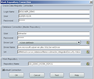
The first time you start the designer you will have to set up the connection to the master repository and work repository, you should be pretty used to this by now and I promise it is the last time you will have to do it. It is the same as when first set up the Topology manager.
The first objective I have set myself to achieve in the designer is to load dimension information from a flat file into the sample planning application, if you have been following then you will have already set up connection information to planning and to the flat file directory in the topology manager.
Before we start make sure you have extracted the KM files (Start KM_) from the impexp directory in the downloaded installation files
Oracle Data Integrator Adapter for Hyperion Planning Release 9.3.1.1 Installation files
KM_IKM SQL to Hyperion Planning.xml
KM_RKM Hyperion Planning.xml
Oracle Data Integrator Knowledge Module for Essbase Release 9.3.1.1 Installation files
KM_IKM SQL to Hyperion Essbase (DATA).xml
KM_IKM SQL to Hyperion Essbase (METADATA).xml
KM_LKM Hyperion Essbase DATA to SQL.xml
KM_LKM Hyperion Essbase METADATA to SQL.xml
KM_RKM Hyperion Essbase.xml
Extract them to %ODI_HOME%\oracledi\impexp
This is just so all the knowledge modules are stored in one place and simpler for importing.
Once you are in the designer, the first thing to do is create a new project.
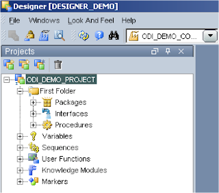
You will notice most of the components I described earlier have been created.
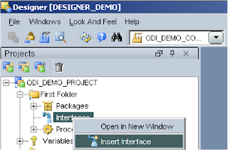
At the moment all we are going to do is import the required KMs, right click the project name (ODI_DEMO_PROJECT) and select Import Knowledge Modules. Select the folder %ODI_HOME%\oracledi\impexp and a full list of the KMs available should be displayed.
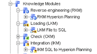
As the first objective is just to use a flat file and planning we will require the following KMs
RKM Hyperion Planning (reverse engineer the planning application)
LKM File to SQL (load data from a file to a temp area using SQL, the temp area is controlled by the Sunopsis memory manager)
IKM SQL to Hyperion Planning (move the data from temp area and load it into the planning repository using SQL)
You may have been wondering what the format of your flat file needs to be and this is where the RKM for planning comes in, setting up the RKM is done in the models area.
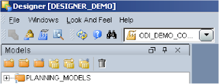
First you need to create a models folder, it is nothing more than a folder and lets you maintain your models. Click the Models tab then Insert Model folder (first button) and finally give it a name.
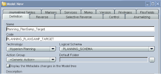
Next step is to insert a model, the first model to set up is a data store to hold all the reverse engineering of the planning app dimensions, when you insert the model you have to name it and choose the technology, in this case it will be Hyperion Planning, on selection the logical schema will be populated with the schema named you applied in the topology manager.
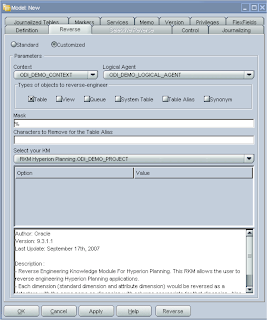
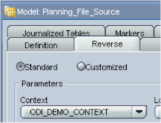
Now on to the reverse tab, this is where the clever KM will be used to reverse engineer the planning dimensions.
Select Customized; choose the context and Logical agent (all of these have been set up from the previous ODI blog)
Select RKM Hyperion Planning from the KM dropdown; it will have the project name appended to it.
Apply the changes and click Reverse and let the KM does its magic.
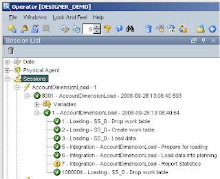
How do you know it has completed? Well a couple of ways, just watch task manager and wait for the CPU process to complete or officially look in the Operator, now you shout what the hell is the Operator. The operator is basically a GUI that displays the status of executions from ODI and are carried out through the use of the Agent.
I am not really going to go into any more detail about the Operator until later in the series when most of the integrations are complete, but for now you can access it from the start menu or directly from each ODI application, in the designer – Windows > Open Module > Operator.
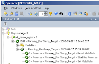
So it looks like our reverse has completed successfully.
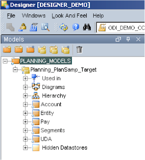
If you expand the model you see each of the available dimensions have been reversed and placed in a datastore with the same name as the dimension, there is also an extra store for the UDA.
At present you cannot reverse engineer or load to Year/Period/Version/Scenario that is just like HAL.
Just to point out I have a couple of occasions where the reverse says it has completed but not all the dimensions in the datastore have been populated, if this is the case just run the reverse again.
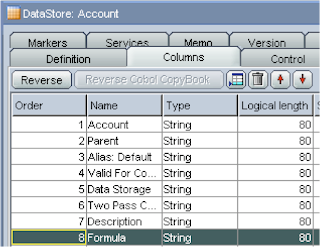
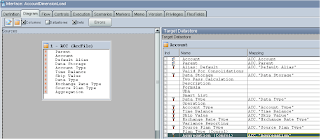
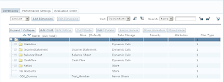
Expanding a datastore such as Account and then columns, the fields that can be populated will be displayed.
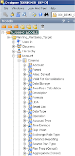
This is where is should start to click in your mind what you are trying to achieve, from a flat file you want to populate some of the above fields which will then be loaded into your planning app, which fields you populate is up to you but obviously Account (member)/Parent are required if you don’t populate the other fields then defaults will be used.
Most of the fields are self-explanatory and relate straight to planning, if you have ever used HAL they will be very familiar. If you have never used HAL then the one that stands out the most is the Operation field.
Operation can have the following values.
Update – This is the default and is used if not populated, it Add, updates, moves the member being loaded.
Delete Level0 - Deletes the member being loaded if it has no children
Delete Idescendants–Deletes the member being loaded and all of its descendants.
Delete Descendants–Deletes the descendants of the member being loaded, but does not delete the member itself.
Just a slight deviation but I am just going to demonstrate what happens when you have not set up the connection to the planning app in the topology manager, I just renamed the planning app from plansamp to plansamp1 in the topology manager and ran the reverse again.
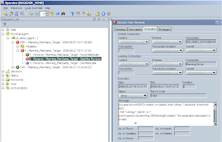
I have found with ODI that sometimes the error messages are pretty obscure, this one is one of the better ones “The application plansamp1 is invalid” gives you a rough idea, though this is the first opportunity that you have had to check you set up the connection correctly.
So now we have reversed our dimensions a csv hierarchy load file can be created. If you like you can just create a file with headings that relate to all the reversed fields.
For an example say I was going to add the following member as a child of account
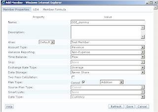
The csv file would look like this :-

From this you should be able to build up a file to match your planning application pretty easily, once you have completed the file make sure you save it in the file store directory you set up in the topology manager, in my case “E:\FileStore\AccLoad.csv”
Now we have to create a model and datastore that will pick up the file.
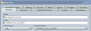
Choose File as the technology and choose the logical schema you created originally in the topology manager.
In the reverse tab select your context.
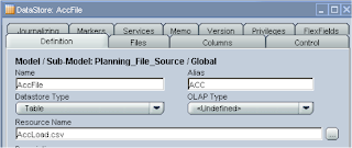
Insert a new DataStore and give it a name and if you click browse for file button it should open up in the correct directory and you can select the csv file.
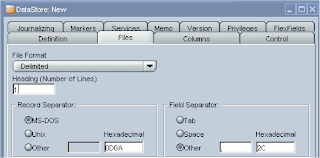
In the files tab as we are using a CSV file then choose Fie Format as delimited, the file has a header row so it was set to 1, the field separator was set to other and as a comma (,)
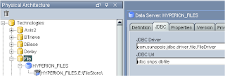
If you have been following this guide then you may have to go back into the topology manager as I forgot to set the JDBC options for the File set up, I have corrected the previous blog but this is what you need to make sure you have set.
Back to the designer, click the Columns tab then the Reverse button and all being well the file structure should be retrieved.
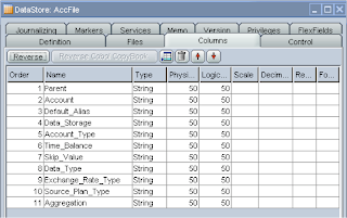
One thing to watch out for if you are using formulas, the physical and logical length is set to 50 and formulas can easy surpass that so you will need to increase the length and in the reversed dimension column set up which is defaulted to 80.
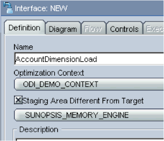
Ok we have created the source and target elements so now we have to put them together to bring them together and this is done by creating an interface, back to the projects tab and insert a new interface
Give it a name and make sure the context is selected, next check “Staging Area Different From Target” and choose “SUNOPSIS_MEMORY_ENGINE”.
This allows any transformations between the source and target to be handled by the memory engine, an example being if you have a column header named TB in the source file and in the planning target it goes to Time Balance then the memory engine will handle this mapping.
On to the Diagram tab, this is where you drag and drop you source and target datastores, its certainly not the best graphically designed section and I remember thinking it was hideous the first time I saw it.
First drag you Account Flat file datastore from the models window into the source window and then drag the reversed account dimension datastore into the target window, select yes for the automatic mapping. What this will do is automatically map the column headings of your file to the target planning dimension, if you create the file with exactly the same headings as the dimension properties then you will have less work to do.
Anyway you should end up with this lovely looking organised window.
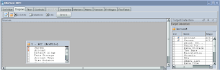
Just stretch the windows to make it more appealing and understandable.
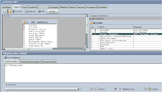
Now we have to map the remaining source and targets, the ones that have been mapped will show as red in the source, btw the “S” in the source/target windows stands for String as all the fields we are using are String based. In the target window the members that have been automatically mapped will be displayed with an icon that stands for Source so basically meaning the source is the same as the target.
To map, click on a name in the target window, this should display the mapping window below, tick the “Active Mapping” box and in the implementation window enter the 3 digit name of the source and the column name, so for the Target of “Alias: Default” the implementation window will have ACC.”Default_Alias”, finally click the “Staging Area” button, as we need to use the sunopsis memory engine to perform the mapping.
If you like you don’t have to manually enter the name, you can click the “Launch Expression Editor” and select from the window.
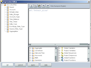
The expression editor has a whole raft of functions that can be used but you won’t probably use them for basic mappings.
The process needs to be repeated for the remaining source properties.
You can also force the value in the target mapping to be a fixed value, so say everything was going to be put against a “Source Plan Type” of Consol you wouldn’t need that in your source file and you can just enter the value into the mapping like so :-
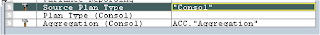
If you are going to do this make sure the “Active Mapping” box is ticked and execute on the staging area is selected.
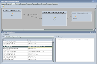
Once you have completed all the mappings click on the Flow tab and a diagram should be displayed outlining the process, if you click on the Target there are a number of options available like setting up error logging and the ability to refresh to essbase after the load has completed.
After applying changes you can execute the interface and the data in the file should be loaded into planning, you can check in the Operator to see how the process went.
You should also check the log files that were generated, you may see this is the log
2008-09-28 13:15:04,109 DEBUG [DwgCmdExecutionThread]: Number of columns in the source result set does not match the number of planning target columns.
I wouldn’t worry about the message, as it is not really an error.
In planning your member(s) should have been loaded.
So there we go we have completed the objective of loading information from a flat file into a planning dimension, from here you should be able to do the same for other dimensions.
I am going to wrap it up there for today, hopefully it all makes sense and you can go off and create your own load interfaces.
Next time I will look into loading data from a SQL table to planning and look at what can be achieved with ODI and essbase.
The main elements to the designer are models and projects; a model is a set of datastores corresponding to data structures contained in a physical schema. In a model you will perform the reverse engineering for instance reverse-engineering the dimensions and properties from a planning application into a readable column format. The RKM (Reverse Knowledge Model) for planning should have already been downloaded (see the first part of the ODI series to find out what you need)
A project is a group of objects developed using ODI, the components to a project are:-
Packages:- A package is a sequence of steps organized into a flow diagram, so say you wanted to wait for a file to arrive, load it into a planning dimension, push it to essbase and then send a successful or failure email then the package is the place for this.
Interface:- An interface is really a set of rules that define the loading of a Datasource from one or more source Datastores, an example of an interface is load members into planning dimension.
Procedure :- A procedure is a reusable component that groups operations that do not fit into the interface category, for example sending a batch of files through FTP.
Variable :- This is a value which is stored in ODI, this value can be set or evaluated to create conditions in packages, it is pretty much what you would expect a variable to be.
Sequence :- A sequence is a variable automatically incremented when used.
Knowledge Modules – I described these in Part 1 of this series so if you need a refresher just have a quick look back.
You will get a much clearer understanding of the different components as we start to use them.
The first time you start the designer you will have to set up the connection to the master repository and work repository, you should be pretty used to this by now and I promise it is the last time you will have to do it. It is the same as when first set up the Topology manager.

The first objective I have set myself to achieve in the designer is to load dimension information from a flat file into the sample planning application, if you have been following then you will have already set up connection information to planning and to the flat file directory in the topology manager.
Before we start make sure you have extracted the KM files (Start KM_) from the impexp directory in the downloaded installation files
Oracle Data Integrator Adapter for Hyperion Planning Release 9.3.1.1 Installation files
KM_IKM SQL to Hyperion Planning.xml
KM_RKM Hyperion Planning.xml
Oracle Data Integrator Knowledge Module for Essbase Release 9.3.1.1 Installation files
KM_IKM SQL to Hyperion Essbase (DATA).xml
KM_IKM SQL to Hyperion Essbase (METADATA).xml
KM_LKM Hyperion Essbase DATA to SQL.xml
KM_LKM Hyperion Essbase METADATA to SQL.xml
KM_RKM Hyperion Essbase.xml
Extract them to %ODI_HOME%\oracledi\impexp
This is just so all the knowledge modules are stored in one place and simpler for importing.
Once you are in the designer, the first thing to do is create a new project.

You will notice most of the components I described earlier have been created.
At the moment all we are going to do is import the required KMs, right click the project name (ODI_DEMO_PROJECT) and select Import Knowledge Modules. Select the folder %ODI_HOME%\oracledi\impexp and a full list of the KMs available should be displayed.
As the first objective is just to use a flat file and planning we will require the following KMs
RKM Hyperion Planning (reverse engineer the planning application)
LKM File to SQL (load data from a file to a temp area using SQL, the temp area is controlled by the Sunopsis memory manager)
IKM SQL to Hyperion Planning (move the data from temp area and load it into the planning repository using SQL)

You may have been wondering what the format of your flat file needs to be and this is where the RKM for planning comes in, setting up the RKM is done in the models area.
First you need to create a models folder, it is nothing more than a folder and lets you maintain your models. Click the Models tab then Insert Model folder (first button) and finally give it a name.

Next step is to insert a model, the first model to set up is a data store to hold all the reverse engineering of the planning app dimensions, when you insert the model you have to name it and choose the technology, in this case it will be Hyperion Planning, on selection the logical schema will be populated with the schema named you applied in the topology manager.

Now on to the reverse tab, this is where the clever KM will be used to reverse engineer the planning dimensions.
Select Customized; choose the context and Logical agent (all of these have been set up from the previous ODI blog)
Select RKM Hyperion Planning from the KM dropdown; it will have the project name appended to it.

Apply the changes and click Reverse and let the KM does its magic.
How do you know it has completed? Well a couple of ways, just watch task manager and wait for the CPU process to complete or officially look in the Operator, now you shout what the hell is the Operator. The operator is basically a GUI that displays the status of executions from ODI and are carried out through the use of the Agent.
I am not really going to go into any more detail about the Operator until later in the series when most of the integrations are complete, but for now you can access it from the start menu or directly from each ODI application, in the designer – Windows > Open Module > Operator.

So it looks like our reverse has completed successfully.

If you expand the model you see each of the available dimensions have been reversed and placed in a datastore with the same name as the dimension, there is also an extra store for the UDA.
At present you cannot reverse engineer or load to Year/Period/Version/Scenario that is just like HAL.
Just to point out I have a couple of occasions where the reverse says it has completed but not all the dimensions in the datastore have been populated, if this is the case just run the reverse again.
Expanding a datastore such as Account and then columns, the fields that can be populated will be displayed.

This is where is should start to click in your mind what you are trying to achieve, from a flat file you want to populate some of the above fields which will then be loaded into your planning app, which fields you populate is up to you but obviously Account (member)/Parent are required if you don’t populate the other fields then defaults will be used.
Most of the fields are self-explanatory and relate straight to planning, if you have ever used HAL they will be very familiar. If you have never used HAL then the one that stands out the most is the Operation field.
Operation can have the following values.
Update – This is the default and is used if not populated, it Add, updates, moves the member being loaded.
Delete Level0 - Deletes the member being loaded if it has no children
Delete Idescendants–Deletes the member being loaded and all of its descendants.
Delete Descendants–Deletes the descendants of the member being loaded, but does not delete the member itself.
Just a slight deviation but I am just going to demonstrate what happens when you have not set up the connection to the planning app in the topology manager, I just renamed the planning app from plansamp to plansamp1 in the topology manager and ran the reverse again.

I have found with ODI that sometimes the error messages are pretty obscure, this one is one of the better ones “The application plansamp1 is invalid” gives you a rough idea, though this is the first opportunity that you have had to check you set up the connection correctly.
So now we have reversed our dimensions a csv hierarchy load file can be created. If you like you can just create a file with headings that relate to all the reversed fields.
For an example say I was going to add the following member as a child of account

The csv file would look like this :-

From this you should be able to build up a file to match your planning application pretty easily, once you have completed the file make sure you save it in the file store directory you set up in the topology manager, in my case “E:\FileStore\AccLoad.csv”
Now we have to create a model and datastore that will pick up the file.

Choose File as the technology and choose the logical schema you created originally in the topology manager.

In the reverse tab select your context.

Insert a new DataStore and give it a name and if you click browse for file button it should open up in the correct directory and you can select the csv file.

In the files tab as we are using a CSV file then choose Fie Format as delimited, the file has a header row so it was set to 1, the field separator was set to other and as a comma (,)
If you have been following this guide then you may have to go back into the topology manager as I forgot to set the JDBC options for the File set up, I have corrected the previous blog but this is what you need to make sure you have set.

Back to the designer, click the Columns tab then the Reverse button and all being well the file structure should be retrieved.

One thing to watch out for if you are using formulas, the physical and logical length is set to 50 and formulas can easy surpass that so you will need to increase the length and in the reversed dimension column set up which is defaulted to 80.

Ok we have created the source and target elements so now we have to put them together to bring them together and this is done by creating an interface, back to the projects tab and insert a new interface

Give it a name and make sure the context is selected, next check “Staging Area Different From Target” and choose “SUNOPSIS_MEMORY_ENGINE”.
This allows any transformations between the source and target to be handled by the memory engine, an example being if you have a column header named TB in the source file and in the planning target it goes to Time Balance then the memory engine will handle this mapping.

On to the Diagram tab, this is where you drag and drop you source and target datastores, its certainly not the best graphically designed section and I remember thinking it was hideous the first time I saw it.
First drag you Account Flat file datastore from the models window into the source window and then drag the reversed account dimension datastore into the target window, select yes for the automatic mapping. What this will do is automatically map the column headings of your file to the target planning dimension, if you create the file with exactly the same headings as the dimension properties then you will have less work to do.
Anyway you should end up with this lovely looking organised window.

Just stretch the windows to make it more appealing and understandable.
Now we have to map the remaining source and targets, the ones that have been mapped will show as red in the source, btw the “S” in the source/target windows stands for String as all the fields we are using are String based. In the target window the members that have been automatically mapped will be displayed with an icon that stands for Source so basically meaning the source is the same as the target.
To map, click on a name in the target window, this should display the mapping window below, tick the “Active Mapping” box and in the implementation window enter the 3 digit name of the source and the column name, so for the Target of “Alias: Default” the implementation window will have ACC.”Default_Alias”, finally click the “Staging Area” button, as we need to use the sunopsis memory engine to perform the mapping.

If you like you don’t have to manually enter the name, you can click the “Launch Expression Editor” and select from the window.

The expression editor has a whole raft of functions that can be used but you won’t probably use them for basic mappings.
The process needs to be repeated for the remaining source properties.

You can also force the value in the target mapping to be a fixed value, so say everything was going to be put against a “Source Plan Type” of Consol you wouldn’t need that in your source file and you can just enter the value into the mapping like so :-

If you are going to do this make sure the “Active Mapping” box is ticked and execute on the staging area is selected.
Once you have completed all the mappings click on the Flow tab and a diagram should be displayed outlining the process, if you click on the Target there are a number of options available like setting up error logging and the ability to refresh to essbase after the load has completed.

After applying changes you can execute the interface and the data in the file should be loaded into planning, you can check in the Operator to see how the process went.

You should also check the log files that were generated, you may see this is the log
2008-09-28 13:15:04,109 DEBUG [DwgCmdExecutionThread]: Number of columns in the source result set does not match the number of planning target columns.
I wouldn’t worry about the message, as it is not really an error.

In planning your member(s) should have been loaded.
So there we go we have completed the objective of loading information from a flat file into a planning dimension, from here you should be able to do the same for other dimensions.
I am going to wrap it up there for today, hopefully it all makes sense and you can go off and create your own load interfaces.
Next time I will look into loading data from a SQL table to planning and look at what can be achieved with ODI and essbase.
No comments:
Post a Comment